
‹
›
‹


›
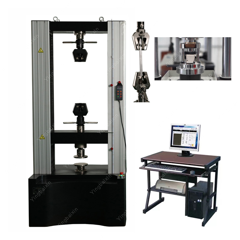
1. Product Overview
The WDW-100B microcomputer controlled electronic universal testing machine is mainly used for compression, bending and other tests of metallic materials, non-metallic materials, etc., and meets the requirements of GB/T 228.1-2021 "Tensile testing of metallic materials - Part 1: Room temperature testing method". Suitable for production and manufacturing, quality supervision, higher education institutions, research institutes, automotive parts, steel metallurgy, aerospace, shipbuilding, military and other fields.
2. Manufacturing and inspection standards for products
GB/T 16491-2008 Electronic Universal Testing Machine;
GB/T 2611-2007 General Technical Requirements for Testing Machines;
JJG 139-2014 "Tensile, Pressure, and Universal Testing Machines";
JJG 475-2008 Verification Regulations for Electronic Universal Testing Machines;
GB/T 16825.1 "Inspection of static uniaxial testing machines - Part 1: Inspection and calibration of force measurement systems for tensile and/or pressure testing machines";
GB/T 22066-2008 "Evaluation of Computer Data Acquisition Systems for Static Uniaxial Testing Machines"
3. Main technical indicators
4. Product Introduction
4.1 Host:
Adopting a double space door structure, the lower space is stretched, while the upper space is compressed, bent, or sheared (the test space can be customized according to user testing requirements). The crossbeam undergoes stepless lifting. The transmission part adopts a circular arc synchronous toothed belt and a screw pair transmission, ensuring smooth transmission and low noise. The planetary gear reducer reduction system and precision ball screw pair drive the moving crossbeam movement of the testing machine, achieving seamless transmission.
4.1.1 The host mainly consists of a base, crossbeam, and column. The middle crossbeam can achieve stepless lifting. The column connects the crossbeam into a portal structure, with high strength and good rigidity, ensuring accurate and safe testing.
4.1.2 Guiding mechanism: A column made of four chrome plated optical axes, using high carbon chromium bearing steel SUJ2. The surface hardness can reach 62 ± 2HRC, and the extremely high material performance ensures the stiffness of the entire frame. Adopting Mismi oil-free lubrication bearings to ensure smooth and long-term high-speed operation.

4.1.2 Motor selection: Panasonic servo motor from Japan: can achieve the industry's fastest response frequency of 2.0kHz, with fast response speed; Smooth movement of the crossbeam, no vibration when stopped, effectively reducing high-precision positioning time, low noise during operation, equipped with the latest controller of the times, controllable speed can achieve the highest level of stable speed in the industry; The protection level meets the TP67 standard, making it more adaptable to the environment.

4.1.3 Reduction system: Adopting a combination of planetary gear reducer and arc synchronous toothed belt reduction method; Precision helical gear transmission, smooth and stable operation, with a backlash of less than 5 minutes between teeth, equipped with precision pre tensioned ball screws to ensure zero error in the forward and reverse operation of the crossbeam. The gearbox uses high-quality and high viscosity lubricating oil to effectively prevent leakage, and there is no need to replace lubricating oil during the product's lifecycle, which is maintenance free for life.
.png")
4.1.4 Sensor: The sensor imported from the United States is from the Shiquan brand, with high accuracy and long service life. The external material is made of stainless steel, which has good waterproof performance and a protection level of up to IP67.
.png")
4.1.5 Transmission system: Precision double nut pre tightening screw is selected, with precise pre tightening force control, eliminating transmission clearance, grinding to ensure accuracy, heat treatment process to ensure raceway hardness, smooth transmission of screw, low noise, long service life, and lifelong maintenance free.
.png")
4.1.6 Appearance: The outer cover of the host is made of aluminum alloy material, which is extruded in one go, with high hardness, good rigidity, and no deformation. The surface is treated with frosting, making it overall beautiful and durable.
4.2 Control System:
4.2.1 The single channel fully digital CTS 7.0 servo controller serves as the system controller. The control system is used for this equipment as an independently developed advanced test system, which can fully ensure the progressiveness and reliability of the system.
4.2.2 A specialized test controller developed using advanced surface mount technology (SMT) and processes, combined with on-site programmable gate array (FPGA) technology, multi-layer circuit board technology, optoelectronic isolation technology, and contemporary analog circuit highly integrated technology. This controller integrates functions such as weak signal processing, A/D conversion, digital I/O, D/A conversion, pulse technology, and pulse generation (PWM).
The high-resolution feedback sampling and signal conditioning technology of controller
4.2.3 improves the data quality of digital servo controller to a new level. The full range non segmented measurement technology ensures accurate and reproducible measurement data throughout the entire sensor range.
4.2.4 It has protection functions such as overload, overcurrent, overvoltage, displacement upper and lower limits, and emergency stop.
4.2.5 The controller can expand the range of test force measurement by adding load sensors.
4.2.6 Equipped with TMS network interface, capable of transmitting, storing, printing records, and network transmission printing of data, and can be connected to the internal LAN or Internet network of the enterprise.
4.2.7 The electrical control circuit shall refer to international standards, comply with national electrical standards for testing machines, have strong anti-interference ability, and ensure the stability of the controller and the accuracy of test data.
4.3 Accessories
4.3.1 Tensile test attachments: flat jaws 0-7mm, round jaws Φ 4-9 Φ 9-14;
4.3.2 Bending test attachments: 1 set;
4.3.3 Compression test attachments: Dimensions: ф 150 mm, pressure plate hardness: ≥ 58HRC;
.png")
4.4 Software:
This measurement and control software is used for microcomputer controlled electronic universal testing machines to conduct various metal and non-metal tests. It completes various functions such as real-time measurement and display, real-time control and data processing, result output, and report printing according to corresponding standards.
4.4.1 The software ensures that the test operation and data processing comply with the requirements of GB/T228.1-2021 "Metallic Materials Tensile Testing Part 1: Room Temperature Test Methods".
.png")
4.4.2 Adopting a unified interface design, it can be applied to various operating systems such as Win10 and above. The software has a selectable multilingual experimental interface, and a special multilingual module that facilitates users to translate into other language versions. It has powerful analysis and reporting functions. The main experimental interface mainly includes menus and shortcut keys, data display, control, curve display, speed display, and sample information.
.png")
4.4.3 Data display section: The five items of test force, peak force, deformation, beam displacement, and test time can be displayed in real time and can be reset separately;
.png")
4.4.4 The automatic program control mode has an intelligent setting system for testing process control mode, which is provided to professional users for testing programmers. Users can flexibly combine multiple control methods and control speeds according to rules as needed, develop experimental control programs, and store them. The measurement and control software can automatically complete the experiment according to this program. Users can pre program and store several experimental programs, which can be accessed through a dropdown menu during use. The experimental software sends and receives I/O control commands according to user needs, and is equipped with automation equipment.
.png")
4.4.5 The curve display section has real-time display functions for various test curves such as test force deformation, test force displacement, and stress-strain, which can be switched and observed at any time; Equipped with coordinate adaptive function, ensuring that the curve is always in the optimal display state; It is very convenient to zoom in, out, and move curves.
4.4.6 The speed display section can display the speed of test force, beam displacement, deformation, stress, and strain in real time.
4.4.7 The sample information section can display relevant information such as sample material, number, sample size, etc. Can communicate with the scanner for data and read information.
.png")
4.4.8 Permission management, with different levels of operators having different operating permissions and different operable menus, effectively protects the entire system;
4.4.9 Analyze data through human-computer interaction. The processing method meets the requirements of GB/T 228.1-2021 "Metallic Materials Tensile Testing Part 1: Room Temperature Test Method", which is widely used. It can automatically calculate various performance parameters such as elastic modulus, yield strength, and specified plastic elongation strength;
4.4.10 Test report: Test data storage, retrieval, and statistical analysis functions, which can be exported to formats such as Word, HTML, Excel, etc., and test reports can be printed in batches;
4.4.11 It can automatically recognize and support remote control box jog control (beam up and down), making it convenient for sample clamping and other operations;
4.4.12 Equipped with automatic shutdown function for testing force overload protection.
4.4.13 It can intelligently determine the fracture of the sample and automatically stop the machine.
4.4.14 The software can intelligently recognize the upper and lower limits of the crossbeam and emergency stop signals, and provide protection. And the software display status is consistent with the actual operating status of the host's crossbeam. After protection, the crossbeam can be directly operated through software to move in the opposite direction and disengage from the limit position, without the need for manual removal of the mechanical limit position.
4.4.15 When conducting batch tests, the data of each sample can be automatically stored after the test is completed, and it will automatically enter the next test to complete the entire batch of tests in sequence.
5.Main product configurations:
 WDW-50B 100B 50kN 100kN 5Ton 10Ton Microcomputer Controlled Electronic Universal Testing Machine
- WDW-5B 10B 20B 5kN 10kN 20kN 0.5Ton 1Ton 2Ton Microcomputer Controlled Electronic Universal Testing Machine
- WDW-100B microcomputer controlled electronic universal testing machine
- WDW-200B 300B 200kN 300kN 20Ton 30Ton Microcomputer Controlled Electronic Universal Testing Machine
- WDW-30B 30kN 3Ton Microcomputer Controlled Electronic Universal Testing Machine


Get real-time quotes
Interested? Leave your contact details.